Yultuz: A Tripoli L2 Certification Rocket
CAD OpenRocket Propulsion
As part of my journey toward obtaining my Tripoli Level 2 Certification, I designed and analyzed a high-performance rocket that will fly on a Cesaroni J140P motor, reaching an altitude of approximately 3,000 feet with a maximum speed of Mach 0.4. I started off with the objectives that need to be met to obtain a Level 2 Certification, which are summarized below:
Tripoli Level 2 Objectives
- Written Test: I must complete and pass (>90%) a written test before launching my Level 2 rocket. The test consists of technical and safety questions relevant to rocketry.
- Airframe: I must build the airframe entirely myself and mark important points on the rocket (center of gravity & center of pressure)
- Recovery: I must use parachute recovery
- Motor: I must use a single J, K, or L class motor
- Electronics: Electronics are not required for a certification.
- Certification Flight: I must fly at a Tripoli insured launch with a certifying authority present to witness the flight.
- Post-Flight Inspection: The rocket must be recoverable and able to fly again given another motor.
I used these objectives to motivate a lot of my design choices. A key objective I wanted to highlight was the Electronics requirement. Although electronics are not required, I included one in this project because a Level 2 flight with proven electronic deployment is necessary for a Level 3 certification flight. I am setting myself up for an eventual Level 3 flight by using electronic deployment, even though it adds a level of complexity. Another requirement for a Level 3 certification flight is a detailed documentation of the design, analysis, manufacturing, & testing process. I plan on using this website as a foundation for the documentation process for my Level 3 certification soon after completing my Level 2 certification. By following the Level 2 requirements above and thinking about an eventual Level 3 certification, I successfully designed a certification rocket detailed below.
Overview
The name of the rocket is “Yultuz”, meaning star in my native language, Uyghur. Stars and constellations were the main reason I became passionate about aerospace engineering as I had always been fascinated about the world outside of Earth for as long as I could remember. The rocket itself is about 6.5 feet tall, 4 inches in diameter, and weighs 14 pounds, including the motor. The diameter was chosen because it is a standard within the high-powered rocketry hobby (98mm), and the height of the rocket allows enough space for the motor, electronic payload, parachutes, and even extra subsystems for flexibility. I used OpenRocket for basic rocket layouts and flight simulations, Solidworks for CAD modeling each part, and ANSYS Fluent for CFD simulations.
Nose Cone
The nose cone that will be used is a Von Karman nose cone. The Von Karman nose cone is based on the Haack series shape equation derived by Wolfgang Haack. The equation is shown below where C is the shape parameter:
(Equation here) (http://servidor.demec.ufpr.br/CFD/bibliografia/aerodinamica/Crowell_1996.pdf)
Setting the shape parameter, C, to zero gives the equation for a Von Karman nose cone, which can be imported into CAD as an equation-driven line. The length-to-diameter ratio for this nose cone is 4.5:1 totalling to around an 18 inch long component. The total length is 23 inches to have room for a smoother transition to the body and for a coupler tube to be inserted to connected the nose cone with a body tube.
The nose cone is mostly made out of filament-wound fiberglass, and the tip is made out of aluminum. The fiberglass allows the nose cone to be lightweight, and the aluminum tip was implemented because that is where the hottest point of the rocket would be during flight.
(CAD of nose cone here)
The nose cone is connected to the upper body tube through a fiberglass coupler tube and a mix of a bolted connection and a shear pin connection. A subsystem can be implemented within the coupler tube in the future. The main parachute shock cord is connected to this coupler tube through a U-bolt and a quick link. The recovery system will be explained in further detail in a later section.
Upper & Lower Body Tubes
The upper and lower body tubes are really similar, so I will explain them both in one section. They are both made out of filament-wound fiberglass and are both 17.75 inches long. The upper body tube is connected to the nose cone and the electronics section through coupler tubes and bolts/shear pins. The main parachute system is housed within the upper body tube, while the lower body tube houses the drogue parachute system. The lower tube is between the electronics section and the fin can of the rocket and is similarly connected with coupler tubes and bolts/shear pins. The coupler tube between the fin can and the lower body tube is empty, leaving room for yet another subsystem. This would be a great place for an airbrake system because having the system as aft as possible wouldn’t change the center of pressure drastically during maximum airbrake deployment. But, the airbrakes system is ultimately a project I plan on pushing to the future.
(Insert body tube pictures here)
Electronics
The coupler tube housing the electronics is between the upper and lower body tubes, and it has a one inch switchband in the middle of it. I will drill holes in this switchband to act as a port hole for the altimeters and will also use them to access the switches in the electronics. The forward and aft bulkheads will contain the U-bolts connecting the recovery system, and they will contain the black powder charges for deployment. The amount of black powder used will be determined in future ground tests. There will be a small hole on each bulkhead to feed the wires from the deployment devices to the black powder charge wells.
(Image of coupler tube overview with bulkhead)
The electronics are laid out on a 3D-printed bay housed in the coupler tube between the upper and lower body tubes. The E-bay has two sides, so there is plenty of room for the electronics I will be flying on Yultuz. (MORE DETAILS HERE)
(Insert picture of e-bay here)
More details of the electronics can be found under my Software/Hardware Projects and is linked here: Electronic Payload for Yultuz
Fin Can
The fin can consists of the most aft body tube with the fins, the motor mount tube, and the motor itself. The body tube, motor mount tube, the three centering rings, and fins are all made out of fiberglass. Rocketry-grade epoxy will be used to connect the centering rings to the motor mount tube and the body tube, along with the fins to the body tube. A 3D-printed, one inch diameter coin will be used to create fillets from the epoxy to ensure a smooth transition from fin to body tube.
(Overview picture of fin can)
Fin slots are cut into the body tube, so the fin will be housed slightly inside of the body tube and resting on the motor mount tube. The middle and aft centering rings will be sandwiching the top and bottom of the fins. This configuration strengthens the fins, which will be a relatively high point of failure because the fins will be the first to come into contact with the ground during recovery. Finally, the shape of the fins were determined based on the stability margin of the rocket, which is the difference of the center of gravity and center of pressure in inches from the tip of the rocket divided by the diameter of the rocket in inches. I explain this in more detail in the OpenRocket Simulation section.
(Picture of fin configuration)
The motor mount tube is housed inside of the body tube and is surrounded by three centering rings. It is important to ensure that the motor mount tube is centered with respect to the rocket to ensure a stable flight. The motor will be fed into the motor mount tube and kept in place with a purchased motor retainer from Aero Pack. The last part of the rocket are the two rail buttons, which will be used to mount the rocket onto the launch rail. The bottom rail button is placed one inch from the bottom of the rocket and the top rail button is 12 inches above the bottom rail button. Each of these rail buttons are outside of the centering rings, making it easy to access post-assembly.
(Insert picture of motor tube, centering rings, and rail buttons)
Recovery System
The recovery system consists of a drogue parachute and a main parachute, which will be connected to the rocket with shock cords and deployed through black powder charges. Both the drogue and main parachutes are 4-line, ripstop nylon parachutes from Rocketman and have a coefficient of drag of 0.97, as listed on their website. These parachutes will be housed in Kevlar deployment bags from Rocketman to protect them from the black powder charges during deployment and will be set-up in a way that will release the parachute after separation. The connection points consists of quick links and U-bolts.
(Insert image of parachute layout here)
OpenRocket Simulations
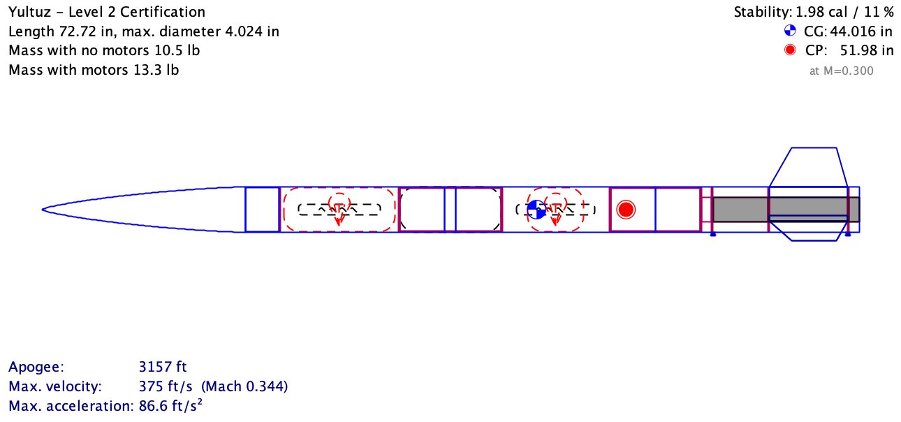
I used OpenRocket, an open source rocket simulator, to design and analyze Yultuz with different simulations and motors. After laying all of the components out, I designed the shape of the fins based on the stability margin. I wanted a stability margin of at least 2 to have enough passive flight control for a steady ascent. With the current design, I have a stability margin of ~2.2 calibers.
OpenRocket Overview of Yultuz
 Next, I used the library of motors that OpenRocket has to select the reloadable motor that I will be using for my certification flight. I wanted a thrust to weight ratio of 5:1 to ensure that the rocket would be at flying speed when it is off the 8 foot launch rail found on the Tripoli Central Virginia launch site. It also needed to fit the motor casing I had, which was a Cesaroni Pro54-3 Grain casing. The motor I ended up on was the Cesaroni J-360, which fits the casing and has a T:W ratio of 6:1. This motor has an ejection charge, but I will be removing it because I already have a dual deployment method for this rocket.
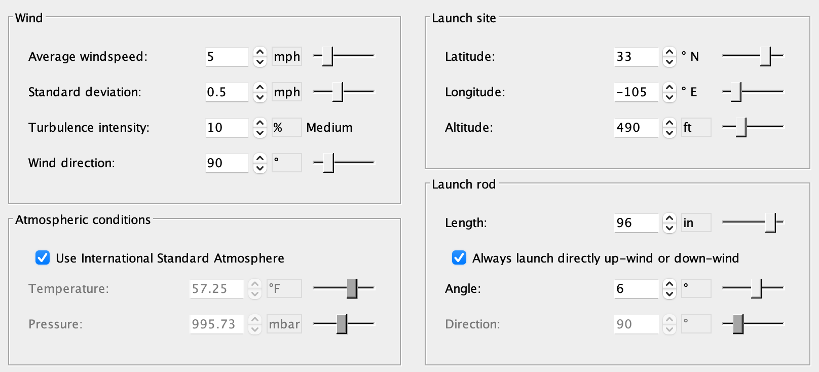
Once I selected the motor, I collected details on the launch site, including the latitude/longitude, some average winds, characteristics of the launch rail, and atmospheric conditions. All of the simulation characteristics are shown in the image below, along with the simulated flight path.
Simulation Parameters
Simulation Plot
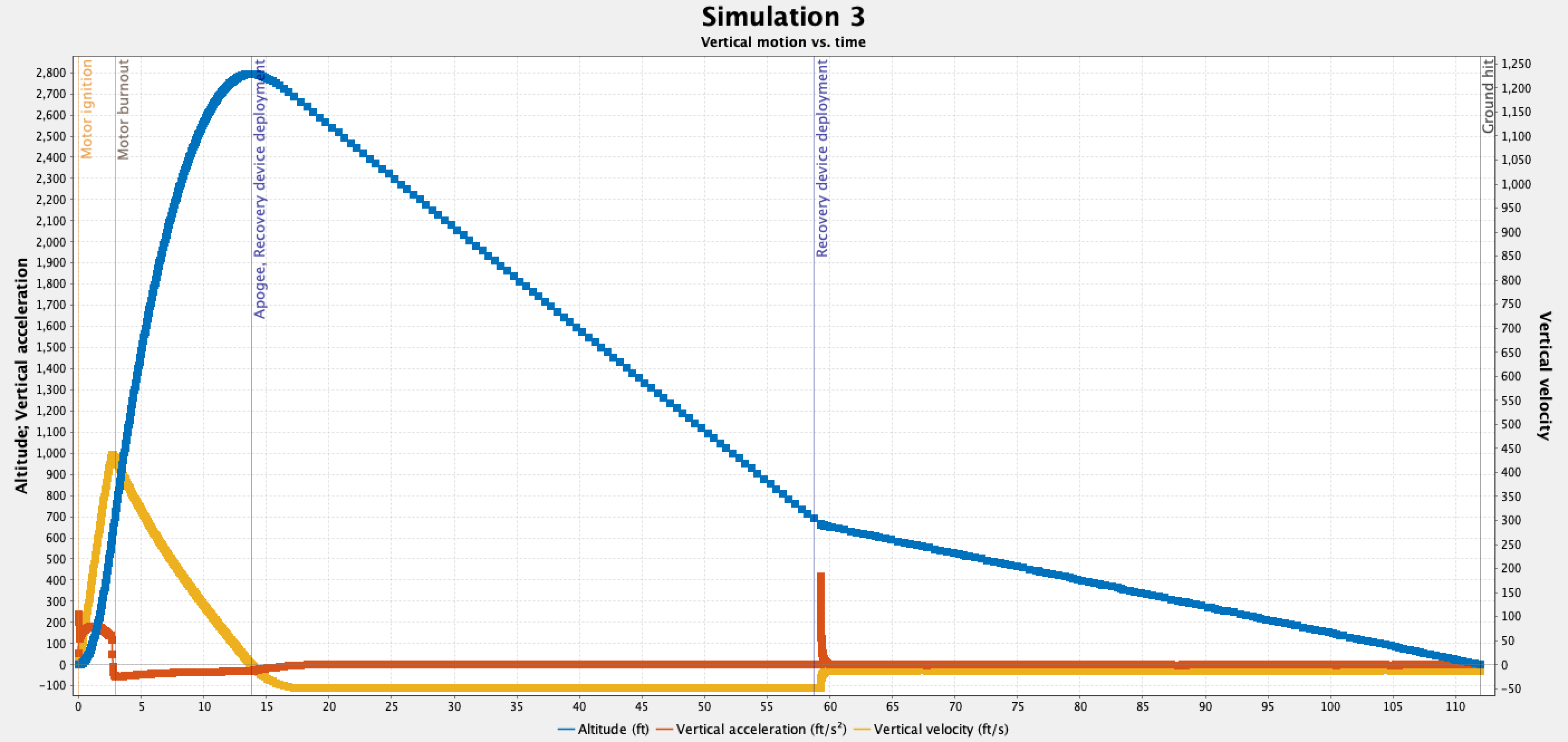 Important details to note are the apogee, velocity off the launch rod, maximum velocity & acceleration, and descent rates under drogue & main parachutes. Each of those values are listed below:
- Apogee: 2794 ft
- Velocity Off-Rod: 49 ft/s
- Maximum Velocity: 448 ft/s
- Maximum Acceleration: 238 ft/s^2 or 7.4 Gs
- Drogue Descent Rate: 47.4 ft/s
- Main Descent Rate: 12.6 ft/s
The velocity off rod paired with the high T:W ratio allows the rocket to achieve a stable speed when getting off of the rod. The maximum acceleration will be used to test the electronic components to ensure that they can survive the high Gs during launch. Finally, the descent rates are low enough that they won’t fall too fast during both phases of recovery and were based off of the recommended descent rates for the International Rocket Engineering Competition Design, Test, & Evaluation Guide.
Budget & Funding
Building a high-power rocket requires careful financial planning. I created budget sheets to track expenses, ensuring that all required components are accounted for before purchase. Currently, I am in the process of raising funds to acquire the necessary materials and avionics.
Next Steps
With the design and planning phase complete, the next steps include finalizing material purchases, assembling the rocket, and conducting ground tests before the official launch. Stay tuned for updates on the build process and launch results!