Capstone Project: Solid Propulsion Motor for a High-Powered Rocket
As the Propulsion Team Lead for my senior capstone design project, I designed, analyzed, and manufactured a student researched and developed propulsion system for a high-powered rocket that my peers were creating in parallel. The main objectives of the capstone project were to successfully launch and recover a rocket with a target apogee of at most 4,000 feet. Many of the comlsponents of a high-powered rocket of this scale are usually outsourced, but the capstone class decided to manufacture most of the components in-house to gain and hone engineering skills. Designing, analyzing, and manufacturing the components added an extra layer of difficulty—especially when coordinating with UVA Environmental Health & Safety—but ultimately led to a final prototype that embodied hours of sound engineering principles and justifications, culminating our undergraduate experience.
Capstone Overview
The whole capstone had a total of around 30 students distributed amongst three teams: Aerostructures, Mechatronics & Controls, and Propulsion. The Propulsion Team that I led consisted of 10 members, and I split those members across 3 sub-teams I created based on the project needs. The sub-teams were Propellant Configuration, Motor Design, and Thermal & Structural Analysis. The Propellant Configuration team eventually became the Motor Selection team after conversations with UVA Environmental Health & Safety (EHS).
Environmental Health & Safety Disclaimer
Initially, the Propulsion Team was planning on manufacturing solid propellant in-house with a formula based off of MIT’s Cherry Limeade, an Ammonium Perchlorate Composite Propellant (APCP). Many system requirements, identified risks, design & analysis work, and manufacturing procedures were created with this in mind. Unfortunately, UVA Environmental Health & Safety restricted us from modifying or manufacturing energetics, leading us to fall back on a couple of our backup plans. I will be explaining the system with the propellant configuration that resulted from the UVA EHS constraints, while mentioning previous iterations whenever necessary.
System Overview
As the Propulsion Team Lead, I developed the system requirements, identified risks of the system, created risk mitigation plans, kept track of the motor’s budget, and used a Gantt chart to create deadlines for critical tasks. The system requirements for the solid motor were based off of the overall requirement of launching the rocket at the Tripoli Central Virginia launch site. This launch site has a maximum apogee constraint of 4,000 feet for rockets that are flying for the first time, so the propulsion system must be able to achieve this while keeping the rocket and engine intact/undamaged.
System Requirements
| Item # | Requirement | Verification Plan | Validation Plan |
|---|---|---|---|
| P-1 | Propulsion system must meet safety standards for storage, handling, transportation, and use. | Review design manufacturing, and handling procedures for safety compliance | Manufacturing tests, static fire tests |
| P-2 | The motor must achieve an altitude of under 4000 feet. | Utilize motor performance software and conduct ground tests to measure thrust | Static fire tests, flight test |
| P-3 | The motor must have reasonable performance specifications | Confirm motor’s design meets performance criteria with analysis tools | Flight test |
| P-4 | The motor must be properly manufactured given time constraints | Ensure that the design is manufacturable | Design reviews |
| P-5 | The motor must be designed to withstand all likely forces and thermal conditions with an acceptable factor of safety. | Perform engineering analyses & simulations to verify design | Static fire tests |
| P-6 | The motor must be designed to ensure the safety of the team in the event of failure. | Review safety procedures during testing | Static fire tests, flight test |
The risks for the propulsion were identified early in the semester. Initially, there were more risks involving the manufacturing, storage, and handling of student researched and developed propellant, but they were no longer necessary once we were given the restriction from UVA EHS.
| Item # | Risk | Description |
|---|---|---|
| RP-1 | Structural Failure | Fails catastrophically, poses safety threat |
| RP-2 | Mis-Design | Inefficient operation or engine failure |
| RP-6 | Motor Misfire | Unintended burn of motor during storage/handling |
RP-1 is mitigated through sound engineering principles and calculations, along with a high factor of safety for different components of the propulsion system. RP-2 is similarly mitigated with engineering principles, along with detailed documentation and drawings for the engine parts. Risks RP-3 to RP-5 were all related to the propellant manufacturing, but these were removed after UVA EHS barred us from working with energetics. RP-6 is mitigated with safe handling, storage, and manufacturing procedures that were laid out beforehand, which consisted of using fire hazard storage systems and training members on manufacturing & handling procedures.
Propellant Configuration & Motor Selection
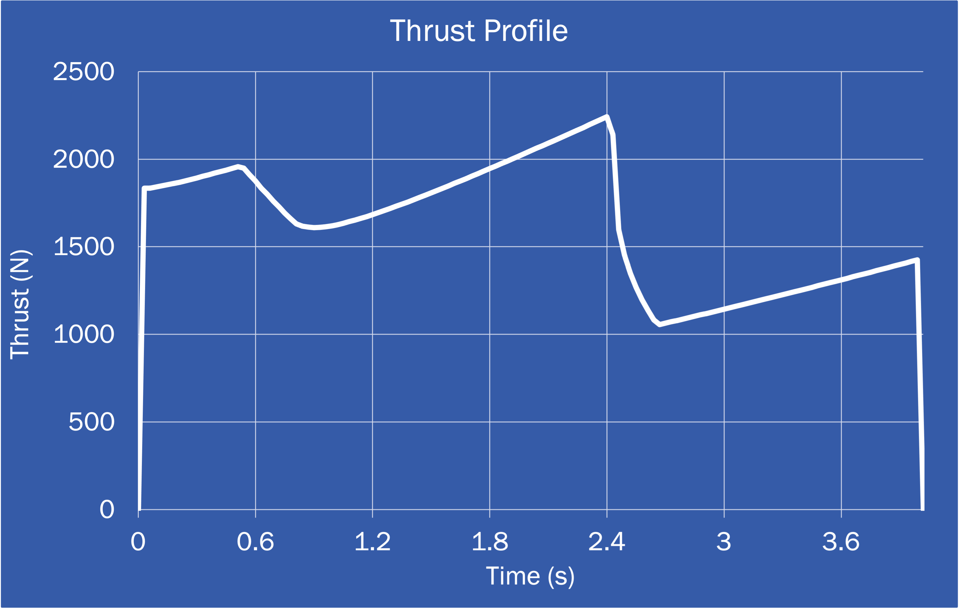
Originally, the initial iteration of the propellant configuration was a mix of a BATES and finocyl grains of student manufactured propellant to achieve a neutral thrust profile while also minimizing erosive burning. Erosive burning is a phenomena where the rapid flowing gas in the combustion chamber sheds some of the propellant surface, leading to inefficient burning and unexpected pressure spikes. The cross-section of those grains and the thrust profile of this initial iteration are shown below.
Thrust Profile and Grain Cross-Section of Initial Iteration

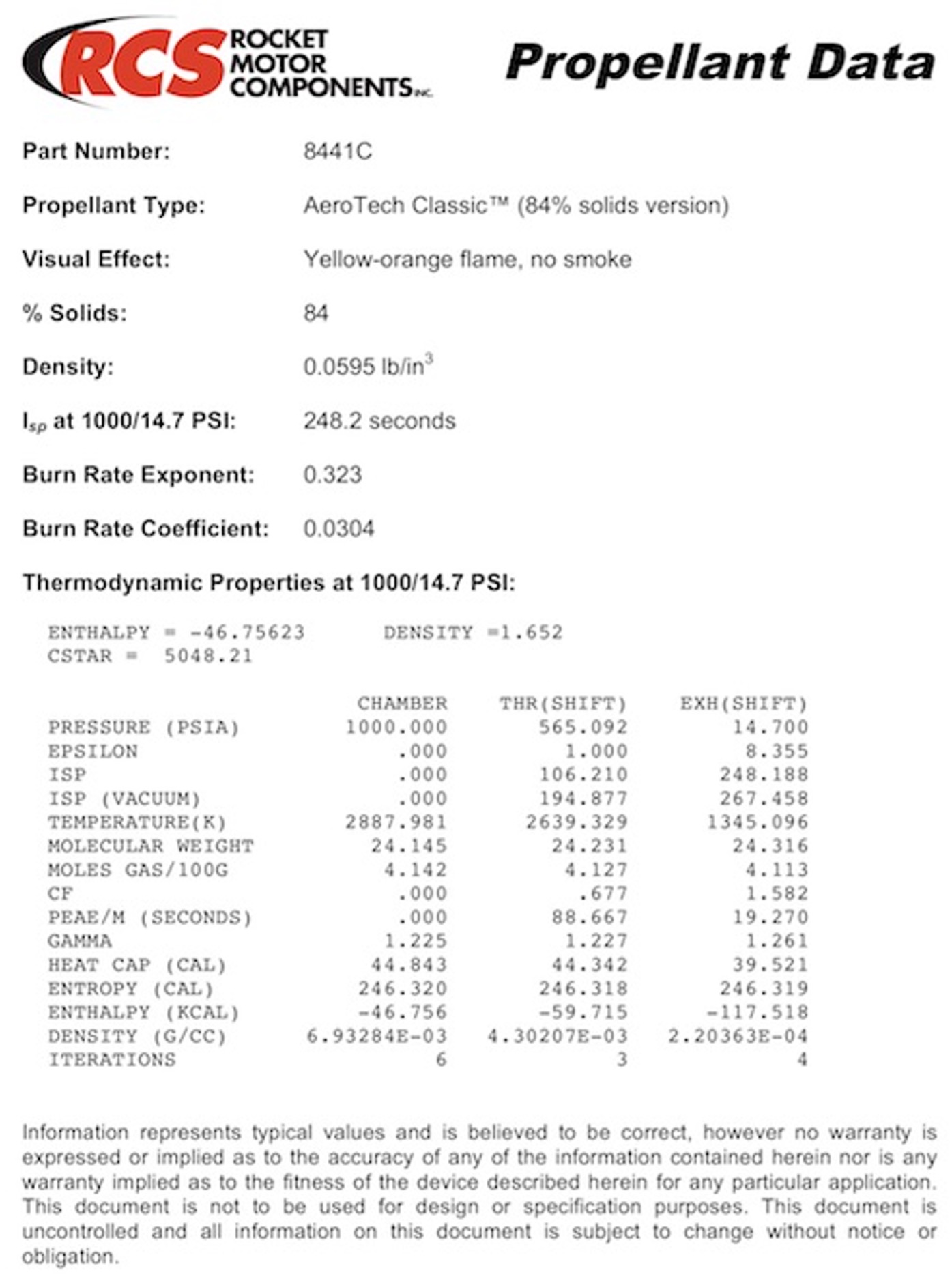
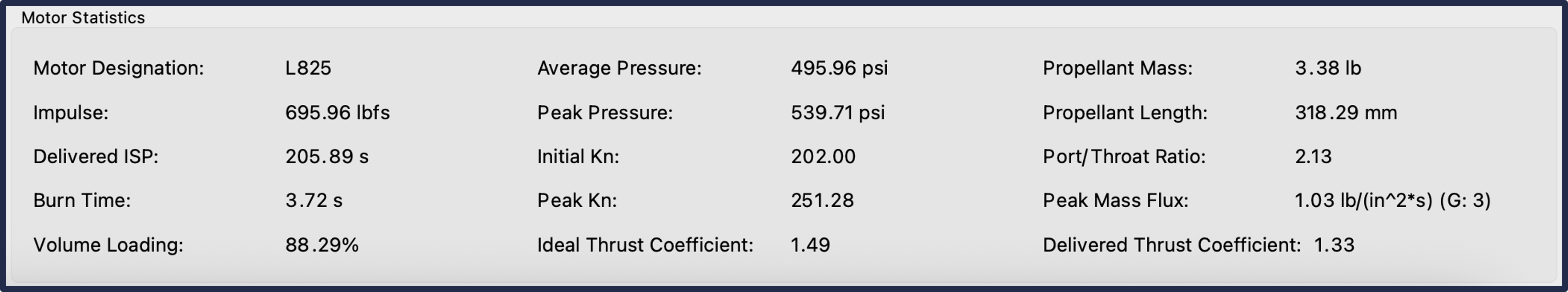
The final iteration of our student researched and developed propellant configuration was a result of meeting the system requirements for the project while complying with the restrictions that UVA EHS had set upon us. We combined open-source propellant burning simulation software (OpenMotor) and commercially available propellant grains to develop a configuration that met the system requirements. The grains would be sourced from Rocket Motor Components and scientific data on the propellants were imported into OpenMotor to analyze performance characteristics of the several propellant options that was available to us. After analysis, the final design was a set of 3 BATES grains of AeroTech Classic Propellant with an outer diameter of 2.493 inches, a core diameter of 0.875 inches, and a length of 4.177 inches to achieve a neutral thrust profile while also meeting other constraints laid out by our technical advisors. Characteristics of the AeroTech Classic Propellant and the motor that we designed are shown below.
AeroTech Classic Propellant Data Sheet
Capstone Propellant Configuration
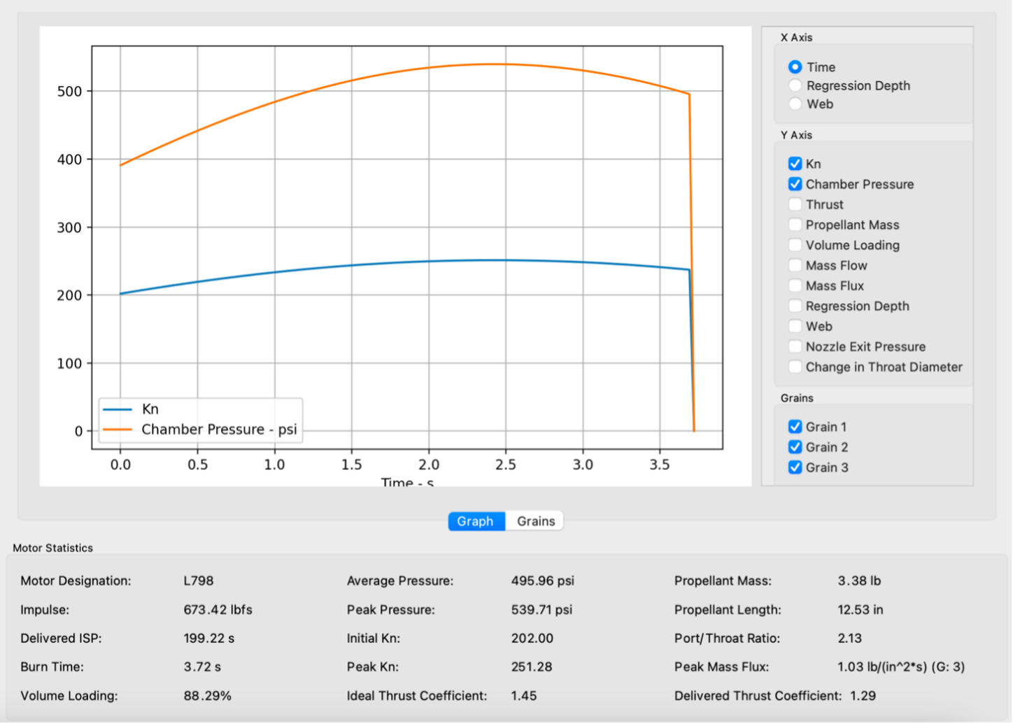
This motor was imported into OpenRocket, an open-source 6DOF rocket simulator to analyze the flight characteristics of the capstone’s rocket with the Propulsion Team’s motor. The simulation parameters were defined by the launch site and the results of the analysis met the requirement of an apogee of less than 4,000 feet, along with other important characteristics. The results of the propellant design and analysis met the system requirements set in the beginning of the year.
Motor Hardware Design
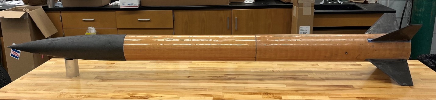
While working on the propellant configuration, I led the engineering of the hardware that would house the propellant and integrate with the rest of the rocket. There were a lot of iterations in this phase of the project, and I successfully led the team through the engineering process to create a full-scale prototype of the motor hardware. I have an exploded view of the motor hardware system below.
Exploded View of Motor Hardware
The motor hardware consisted of the casing, the forward closure, the graphite nozzle, the phenolic liner, and the aft closure/nozzle holder. Additionally, I helped develop a specific nozzle to be used during hydrostatic tests. Starting from the top, the motor casing had a 3 inch outer diameter, 2.75 inch inner diameter, and a height of 20.79 inches. Next, the forward closure had an OD of 2.75in, grooves for two 144 O-rings, a height of 1.67in, and a shoulder for the phenolic liner. Similarly, the aft closure had a 2.75in OD and a 2.25in ID, with a height of 0.5in. These closures are fastened with two internal retaining rings that fit into grooves cut into the inside wall of the casing. The hydrostatic nozzle had the same outer geometry as the nozzle. The only difference was the inside, which was a through hole with a threaded inlet for NPT piping. All of the components, besides the nozzle and liner, are made out of aluminum 6061 for its manufacturability, thermal conductivity, and low costs. The nozzle was made out of graphite for its thermal conductivity and high temperature resistance, although it is harder to manufacture due to it being anisotropic and wouldn’t be used during hydrostatic tests due to it being porous. Regardless, its properties made it a viable material to pursue for the nozzle. Lastly, the liner is made out of phenolic because it is an excellent thermal insulator and resists the high-temperature environment of combustion. Models of the all of the parts, except the liner, are shown below.
CAD Models (images not to scale)
The nuts, retaining rings, and the O-rings were the only things that were purchased and outsourced.
Propulsion System Analysis
Before I got into this section, I wanted to mention an important part of it. Every single analysis that you will see in this section is done entirely by me. I went ahead and improved some simulations from the capstone while adding in new ones using ANSYS skills I learned. I wanted to hone my ANSYS FEA and CFD skills by going into a deeper analytical dive. For each simulation, I was aiming for some certain meshing metrics: An average element quality >0.75, average aspect ratio ~1.000, an average skewness close to 0, and an average orthogonal quality ~1.000.
Casing Structural Simulation
First, I looked at the casing of the motor hardware under the structural loads of the burn. Before I opened up ANSYS, I started with a hand calculation. I knew that the highest stress concentration would likely be near the internal retaining ring grooves because it is the thinnest part of the casing and under a lot of load from the top cap. The hand calculations can be found here: Casing Axial Load Calculations
I brought the casing geometry into a 2D axisymmetric analysis in ANSYS and applied the loads and pressures for a 600 psi burn (rounding up from the max pressure of 540 psi). An image of the ANSYS setup can be seen below:
Loads & Pressure on Casing
I applied a mesh to the geometry and got some of the statistics of the mesh. There were a total of 86,073 nodes (27,260 elements), an average element quality of 0.999, average aspect ratio of 1.027, and an average skewness of 8.98e-3.
Casing Structural Mesh
Finally, I got the results of the simulation, which returned a maximum von-Mises stress of 22,250 psi at the internal retaining ring groove. Comparing that with the yield stress of Aluminum 6061 T6 (40,000 psi), gives a factor of safety of almost 2.
Stress Analysis of Casing
Nozzle Structural Simulation
Next, I explored the structural loads that the nozzle would experience during burn. First, I did a hand calculation using the isentropic flow relations. Details of that hand calculation can be found on my Github page: Nozzle Structural & Thermal Hand Calculation
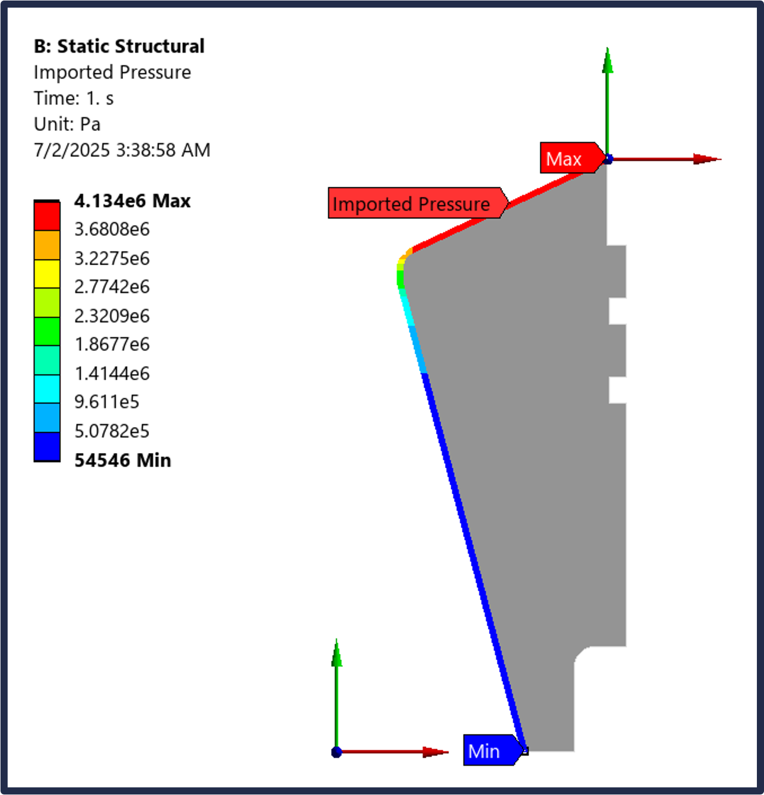
I brought the nozzle geometry into a 2D axisymmetric analysis in ANSYS and applied the pressures for a 600 psi burn (rounding up from the max pressure of 540 psi) by using the isentropic flow relations to find the pressure at each point along the nozzle. An image of the ANSYS setup can be seen below:
Pressures on Nozzle
I applied a mesh to the geometry and got some of the statistics of the mesh. There were a total of 104,795 nodes (34,696 elements), an average element quality of 0.985, average aspect ratio of 1.119, and an average skewness of 4.96e-2.
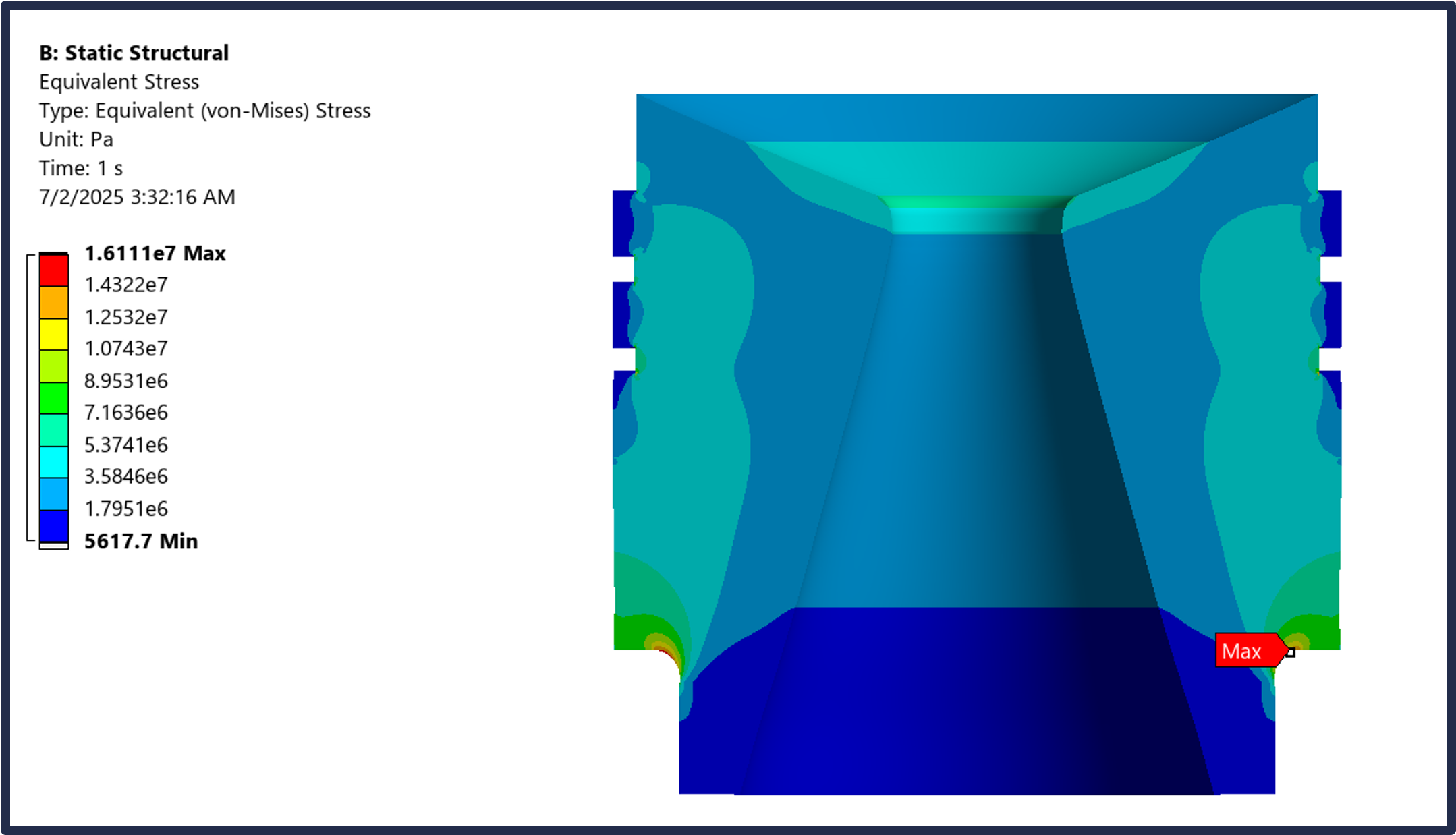
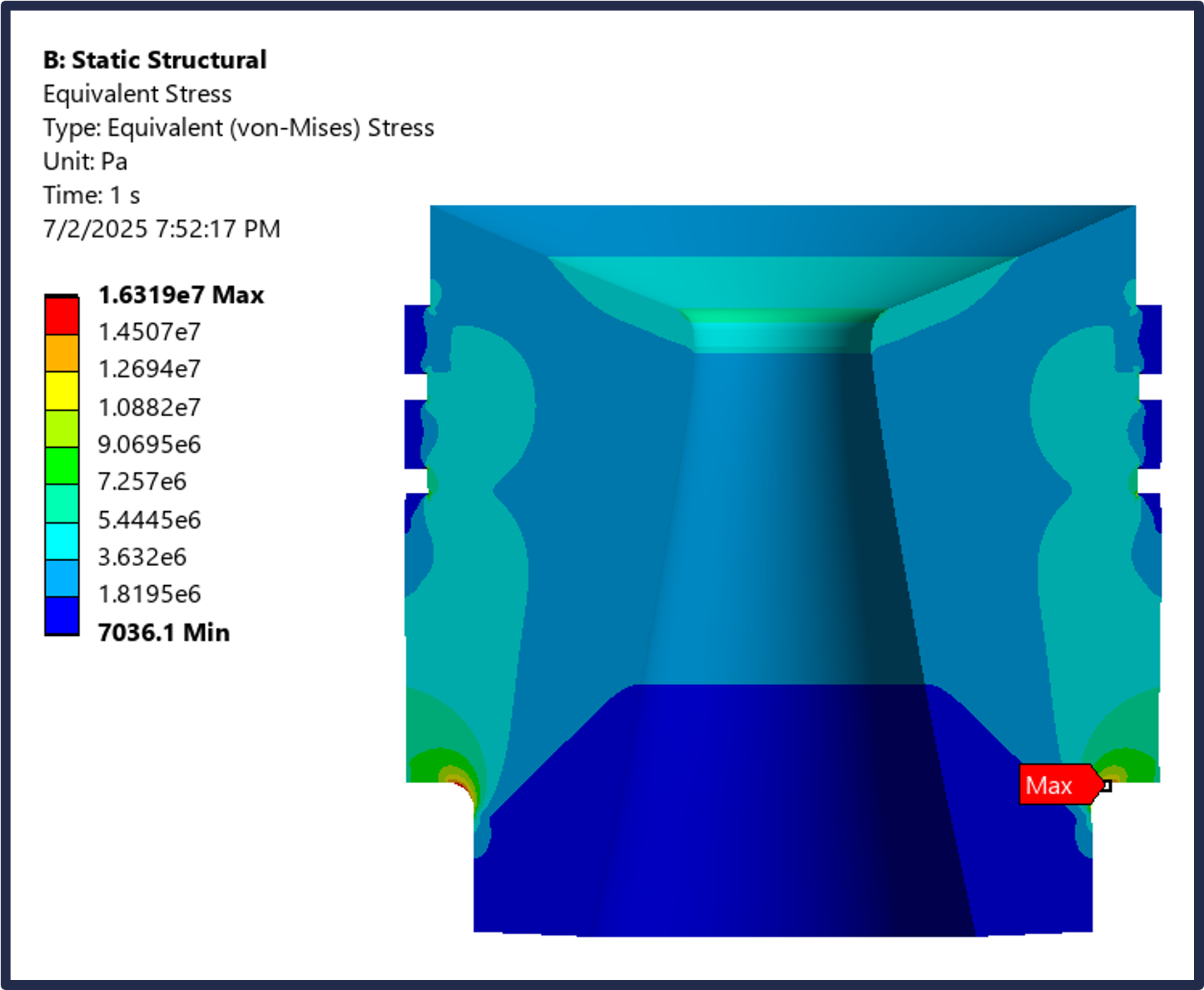
Finally, I got the results of the simulation, which returned a maximum von-Mises stress of 2335.1 psi at the fillet that comes into contact with the nozzle washer. Comparing that with the compressive strength of Graphite (5221.4 psi), gives a factor of safety of more than 2.
Stress Analysis of Nozzle
Liner/Casing Thermal Simulation
Switching gears to a thermal analysis, I analyzed the liner and casing to ensure that the liner would be able to withstand the combustion temperature and protect the casing. First, I gathered the thermal conductivities of the convolute wound paper/phenolic liner and the aluminum casing, which were 0.293 W/m-K and 167 W/m-K, respectively. Then, I executed a hand calculation using the conduction heat flux formula, as seen in this Desmos page: Casing Thermal Calculations
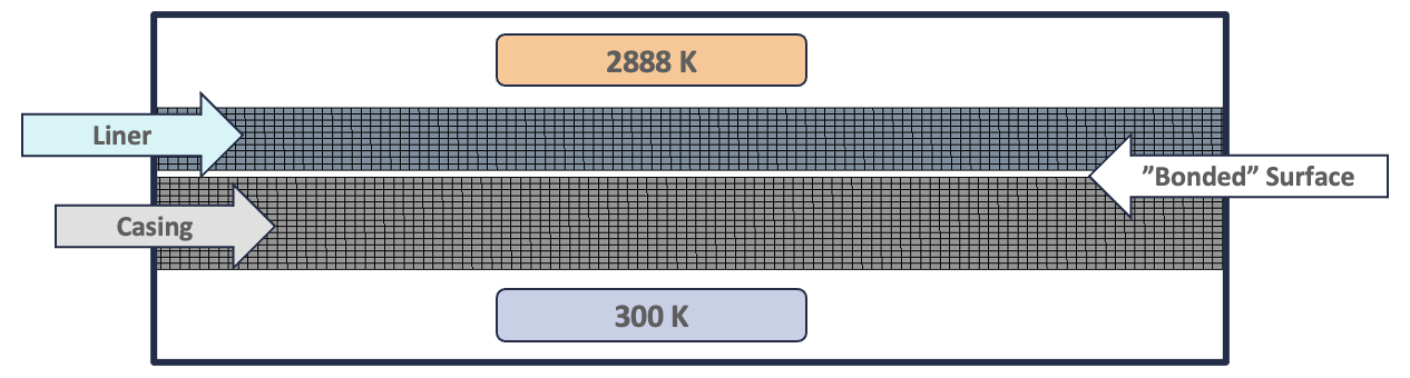
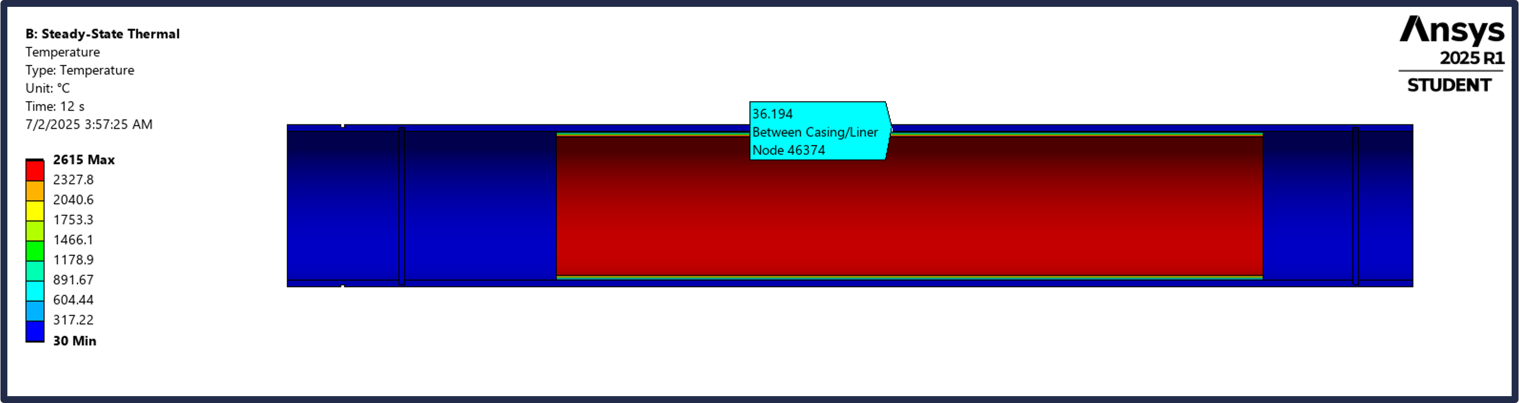
I brought the casing and liner into ANSYS as separate materials with their respective thermal conductivities. Then, I set the temperature inside of the liner to be 2888 K, as per the propellant data sheet, and the temperature outside of the casing to be 300 K as room temperature. Lastly, I bonded the two surfaces between the liner and casing together so that they would be sharing the same temperature during the analysis.
The meshing for this setup consisted of 79,256 nodes (25,038 elements), an average element quality of 0.906, an average aspect ratio of 1.568, and an average skewness of 7.49e-3. Here is an image of the steady state thermal simulation setup:
Casing Thermal Mesh & Setup
Finally, I got the results of the simulation, which returned a temperature of 36.2 degrees C at the surface between the liner and casing, which is well under the 582 degree C melting point of Aluminum 6061 T6. This highlights that the liner will be able to withstand the heat during the motor burn and protect the casing from any thermal damage.
Thermal Analysis of Casing
CFD Simulation
Finally, the last simulation that I conducted was a CFD simulation of the propulsion system at the maximum pressure during the burn. There were a few questions that I had that led me to do the CFD simulation: Will the casing past the nozzle withstand the high temperatures of the exhaust plume? What will the flow past the nozzle look like (over/underexpanded)? Will thrust calculations from the CFD simulation match up with hand calculations derived from isentropic flow relations?
I will start by explaining the setup along with my reasoning in setting certain parameters. Then, I will show the boundary conditions before going into the contours of the plot that will help answer the questions I previously mentioned.
The CFD simulation was done in ANSYS Fluent, and an axisymmetric, density-based solver was used because of the expected high velocities of the fluid. The turbulence model that was selected was the realizable k-epsilon model. This model is good for preliminary looks of the exhaust plume and exit conditions, while also being faster to converge to a solution relative to an SST k-omega model. The assumptions I have are listed below, along with a short explanation:
CFD Simulation Assumptions
- Air is the fluid of the whole domain, including the exhaust plume
- Although the propellant fluid would be different, having one consistent fluid keeps the simulation simple and is good for a preliminary look
- Density determined by ideal gas law
- Compressible flow
- Viscosity determined by Sutherland’s law
- High temperature gradients
- No solid propellant in chamber
- During max pressure, there would still be solid propellant left in the chamber. I didn’t model this because I was mainly focusing on conditions at the exit and past it
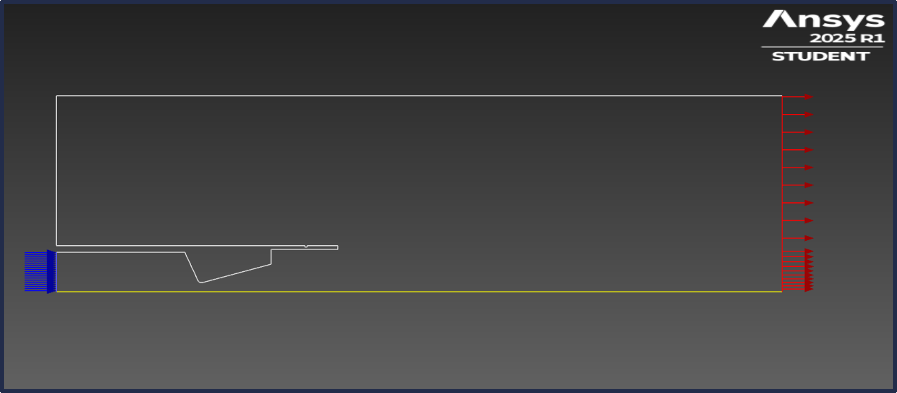
The boundary was a ~24 inch by ~6 inch domain with a pressure inlet of 540 psi, 2888 K and a pressure outlet determined by the US Standard Atmosphere model at 400 ft. The inlet conditions were determined by the OpenMotor simulation and the outlet conditions were selected because the rocket would be near 400 ft. at max burn pressure, according to the OpenRocket model. An initial solution was acquired by doing a 1st order upwind discretization for the turbulent kinetic energy and the dissipation rate, before moving onto a 2nd order upwind discretization for the final solution. This setup helped a lot with convergence for a solution.
CFD Simulation Setup
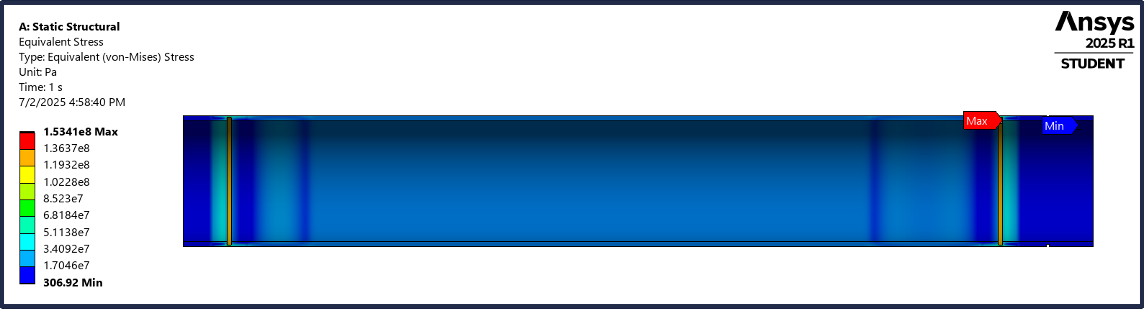
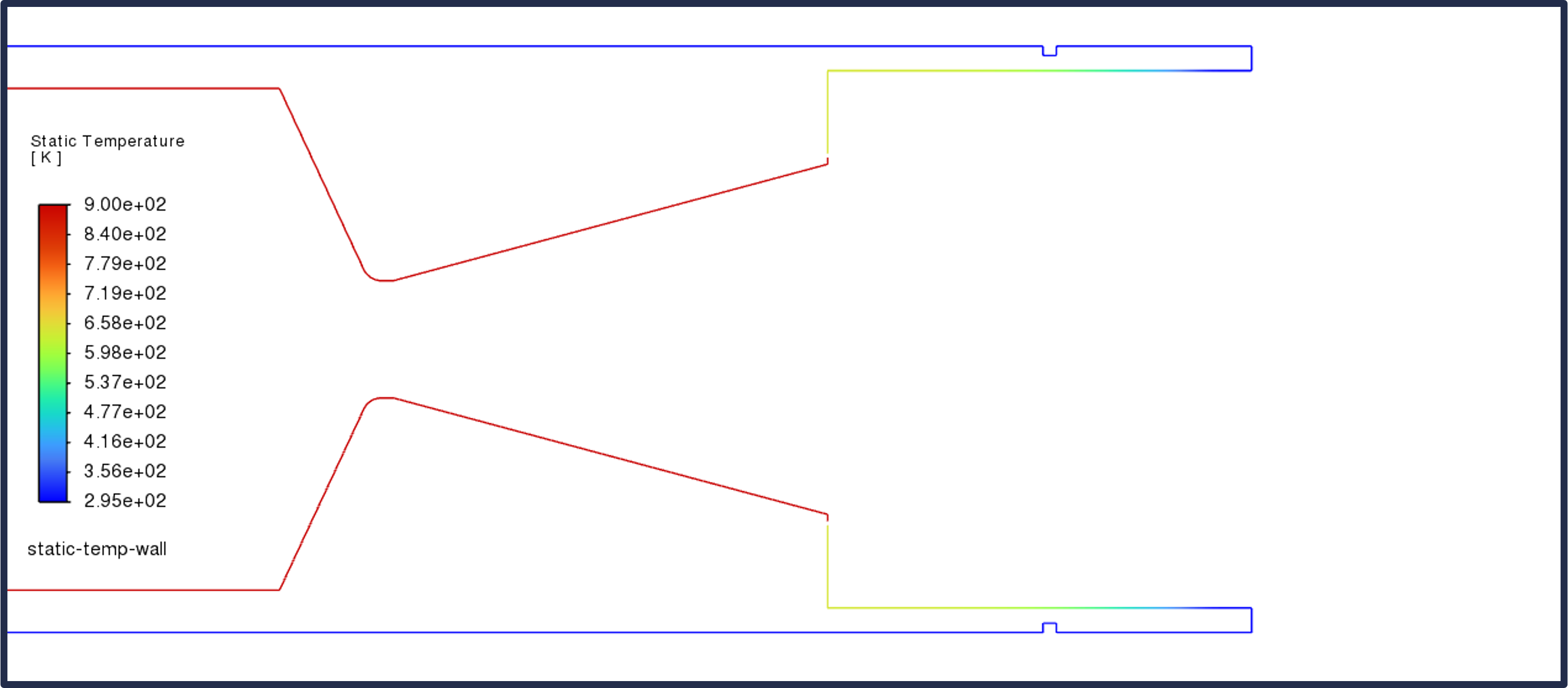
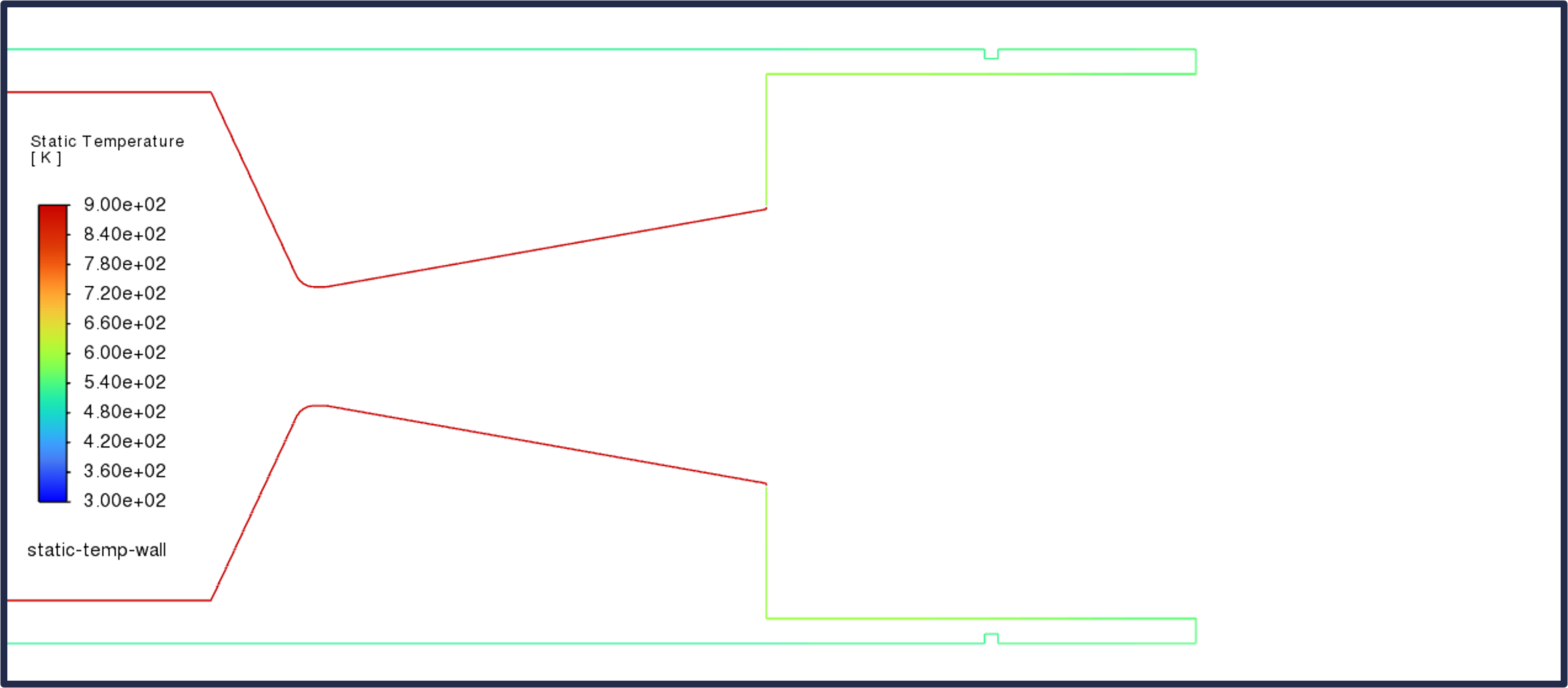
The first contour that I wanted to explore was the temperature along the wall of the casing. According to the results, the temperature along the wall doesn’t exceed 370 degrees C, which is under the melting point of Aluminum 6061 T6 but over the aging temperature. Regardless, I didn’t worry too much about annealing the material because the burn is short enough (~4 seconds) that it shouldn’t significantly alter the microstructures of the aluminum.
Temperature Along the Wall
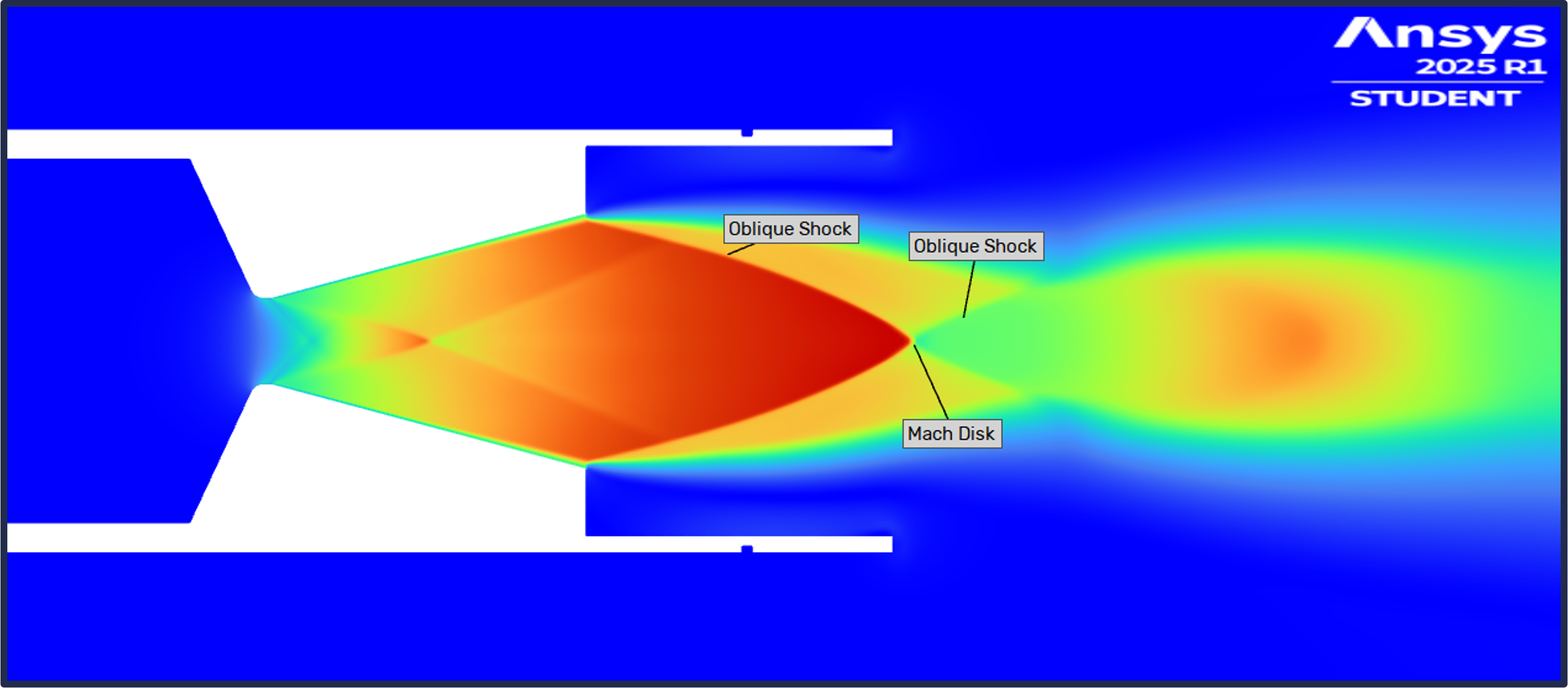
Next, I explored the contour for the velocity in terms of the Mach number. It showed an overexpanded flow past the nozzle, which makes sense because the exit pressure of the nozzle is less than the atmospheric pressure according to isentropic flow calculations.
Mach Number Contour
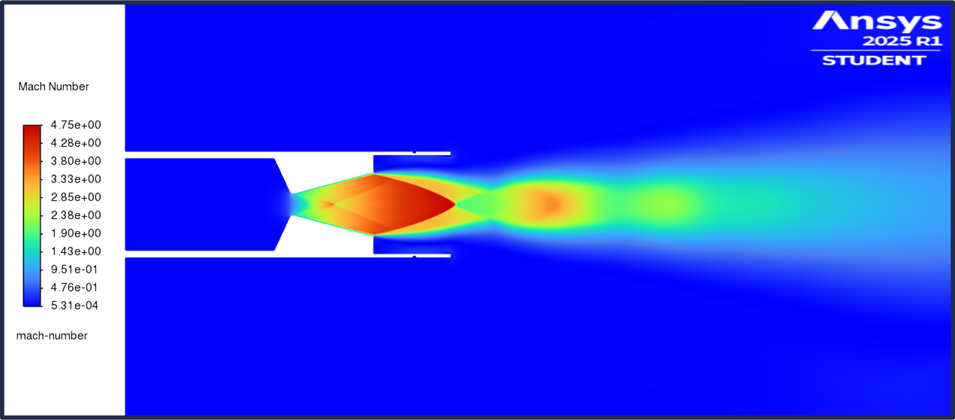
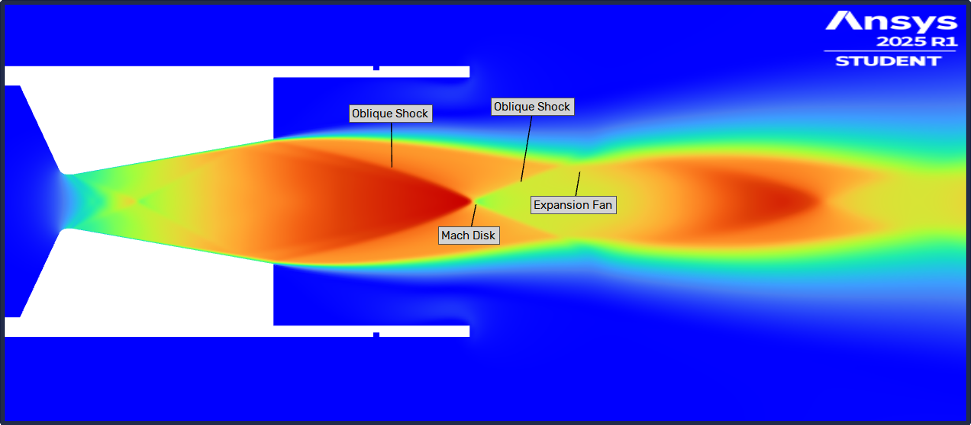
I wanted to take a closer look of the exhaust plume to see if I could identify certain key characteristics of the overexpanded flow. I noticed an oblique shock coming off of the nozzle exit, coming into a Mach disk, before branching off into another oblique shock. Another notable characteristic of the flow is the oblique shock inside of the nozzle. I believe that the sharp angle from the throat to the diverging section is causing an expansion fan to occur which is then reflected off of the wall to create that oblique shock. Adding a fillet to this part of the nozzle would likely prevent this shock from occuring, thereby increasing the efficiency of the flow.
Close-Up of the Mach Number Contour
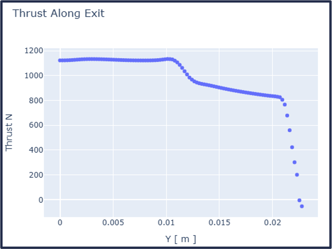
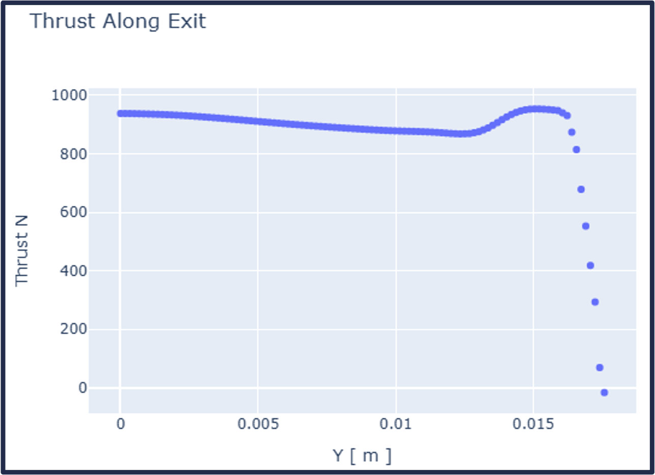
Finally, I did an analysis on the thrust at the nozzle exit while comparing it to a hand calculation I did based on the isentropic flow relations. The hand calculation can be found on this Desmos page: Casing Thermal Calculations. The thrust calculated by hand is 1002.7 Newtons.
I found the thrust at the exit of the CFD simulation by acquiring the necessary exit conditions along the radial axis and used the Thrust Equation: . The graph below shows the thrust along the exit starting from the middle of the nozzle up until the nozzle wall. The average thrust is around 1000 Newtons, which lines up closely with the hand calculations. The significant dip in the middle is likely from the oblique shock that happens inside of the nozzle. This further proves that adding a fillet to the nozzle would increase the thrust by getting rid of the shock.
Thrust Along the Exit
That concludes the analyses that I did for the capstone project. Overall, the propulsion system should be able to withstand the physical and thermal loads during the burn while also providing adequate thrust to bring the rocket to the target apogee of 4,000 ft.
Optimized Nozzle Angle Case Study
A key area of improvement that I noticed during the analysis was that the exit pressure was significantly under the expected atmospheric pressure. I wanted to analyze a theoretical nozzle with a decreased diverging angle to create a more optimized exit pressure, while exploring the effects of the added mass from decreasing the angle. Ultimately, I found that the thrust would be increased and the added mass wouldn’t adversely effect the overall flight trajectory. Key findings are listed below, along with related pictures:
Key Findings of Optimized Nozzle Study
- Adds ~30 grams to the nozzle
- Maximum von-Mises stress is slightly higher (+30 psi) than original nozzle. Still a FoS of 2
- Slightly higher specific impulse and ideal/delivered thrust coefficient
- 100+ ft. increase in predicted apogee
- Cooler temperatures along wall of casing past nozzle exit
- Much better exhaust plume
- Decreased effect of oblique shock within the nozzle
- Higher thrust
Optimized Nozzle Structural Analysis
Optimized Motor Characteristics
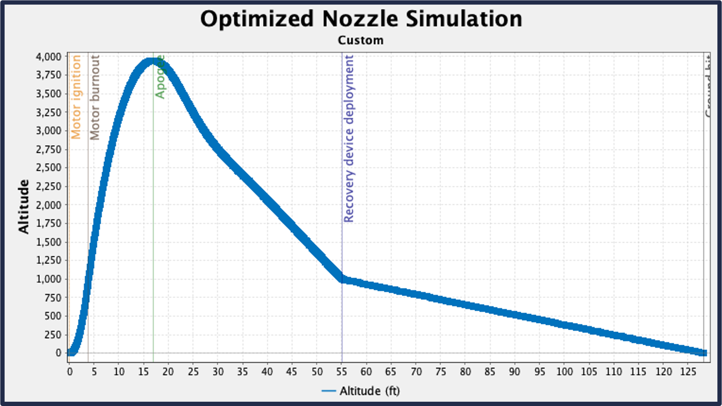
Flight Trajectory with Optimized Motor
Optimized Nozzle Temperature Contour
Optimized Nozzle Mach Contour
Optimized Thrust Along the Exit
Overall, the optimized nozzle is a net-positive for the rocket as a whole because it gets a higher target apogee, has more efficient nozzle flow, and decreases the temperature felt by the casing past the nozzle exit.
Motor Manufacturing
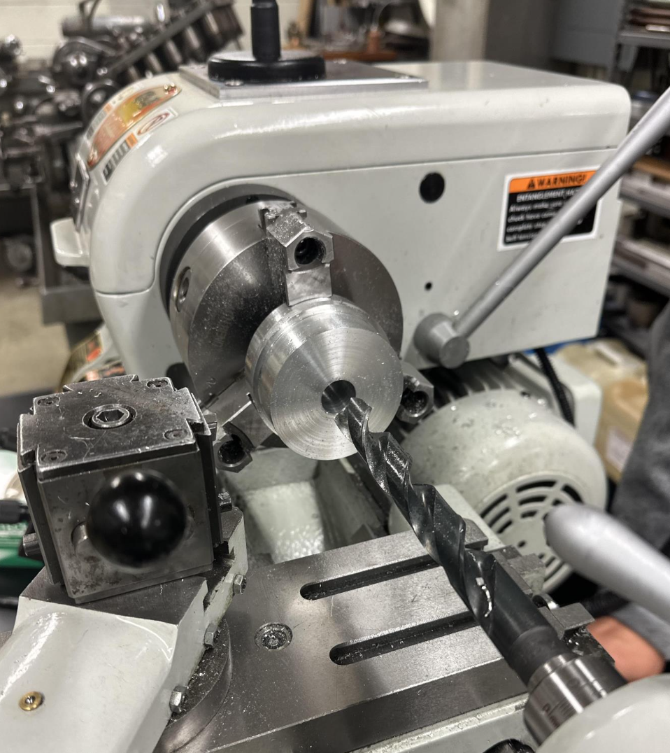
The manufacturing part of the process is where I felt I grew the most as an engineer. Many of the design iterations came as a result of learning lessons during the manufacturing process, including understanding the equipment and experience we had on hand and the importance of balanced tolerancing. One of the designs included a threaded case to secure the forward and aft closures, but it was scrapped because we didn’t have access to a CNC lathe. Another problem was the lack of manufacturing experience within the group, so I, and a couple others, got trained with the shop manager. I learned basic workshop safety procedures and got experience using the bandsaw, vertical mill, and a lathe. After gaining lathe experience, I started working on creating the closures and the hydrostatic nozzle where I ran into another problem. The tolerances we had in our initial drawings were pretty tight, so I went back to the team and let them know of the issue. We reworked the tolerances by identifying which ones were critical and finding out the minimum tolerances we could work with given the tools we had. At the end, we got a product that we could manufacture successfully.
Hydrostatic Nozzle on the Lathe
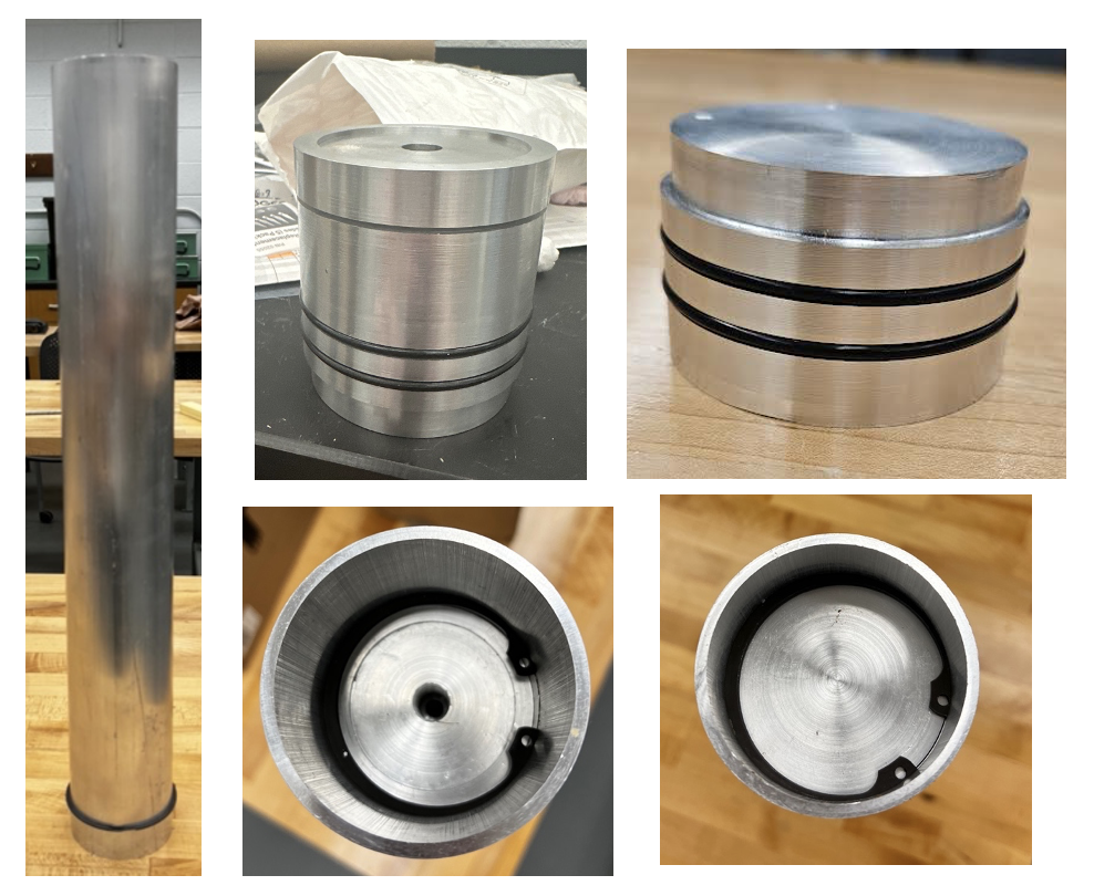
Disassembled and Assembled Pieces
Motor Testing
Two tests were planned for the capstone: a hydrostatic test and a static hotfire. I led the planning for both tests by speaking with an industry professional to get guidance on the hydrostatic test and by collaborating with VCU’s Rocketry Team to use their test stand that they were creating. I created the plumbing diagram for the hydrostatic test and gathered a bill of materials for the equipment necessary to conduct the test.
Hydrostatic Test Plumbing Diagram
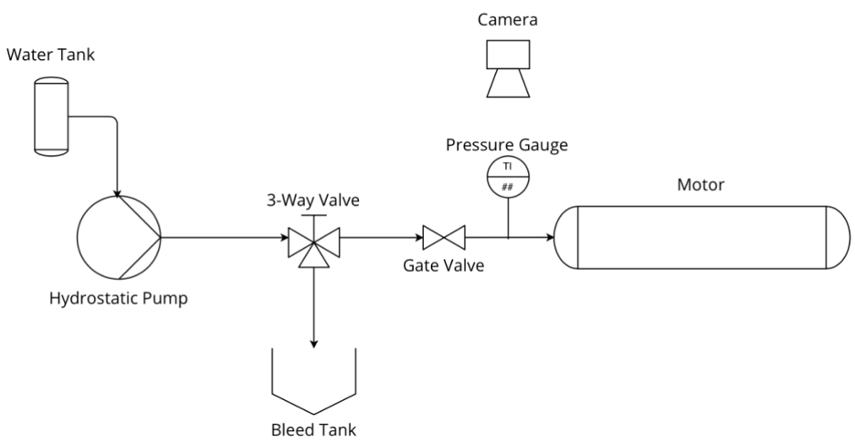
Also, a procedure for the static hotfire was being planned out with VCU because they were creating a test stand that would be able to hold a motor of our size. Unfortunately, due the timing constaints mainly stemming from the UVA EHS restrictions, these tests were not executed.
Final Report
The rest of the capstone was much more than just the propulsion system. A lot of collaboration was required between the other teams, and they did a ton of work for the whole rocket. More details of the whole capstone project can be found in the final report shown below.