Finite Element Analysis & Optimization on a Wheel Flange
CAD FEA
For my final project in Finite Element Analysis (FEA), I optimized a wheel flange to minimize weight while ensuring the part remained within allowable deformation and yield stress limits. I combined simulation techniques with practical design considerations using a mixture of Solidworks and ANSYS, mirroring real-world engineering challenges.
Design Motivation and Initial Approach
To give the project a real-world context, I created a scenario in which a NASCAR racing team was aiming to reduce component mass in order to gain a competitive performance edge. I based my model on a wheel flange from a Ford Mustang, using estimated dimensions and geometries from images I found online. During this phase, I modeled everything in Solidworks, a CAD software, and imported the geometries into an ANSYS workbench to do initial FEA.
Optimization Process
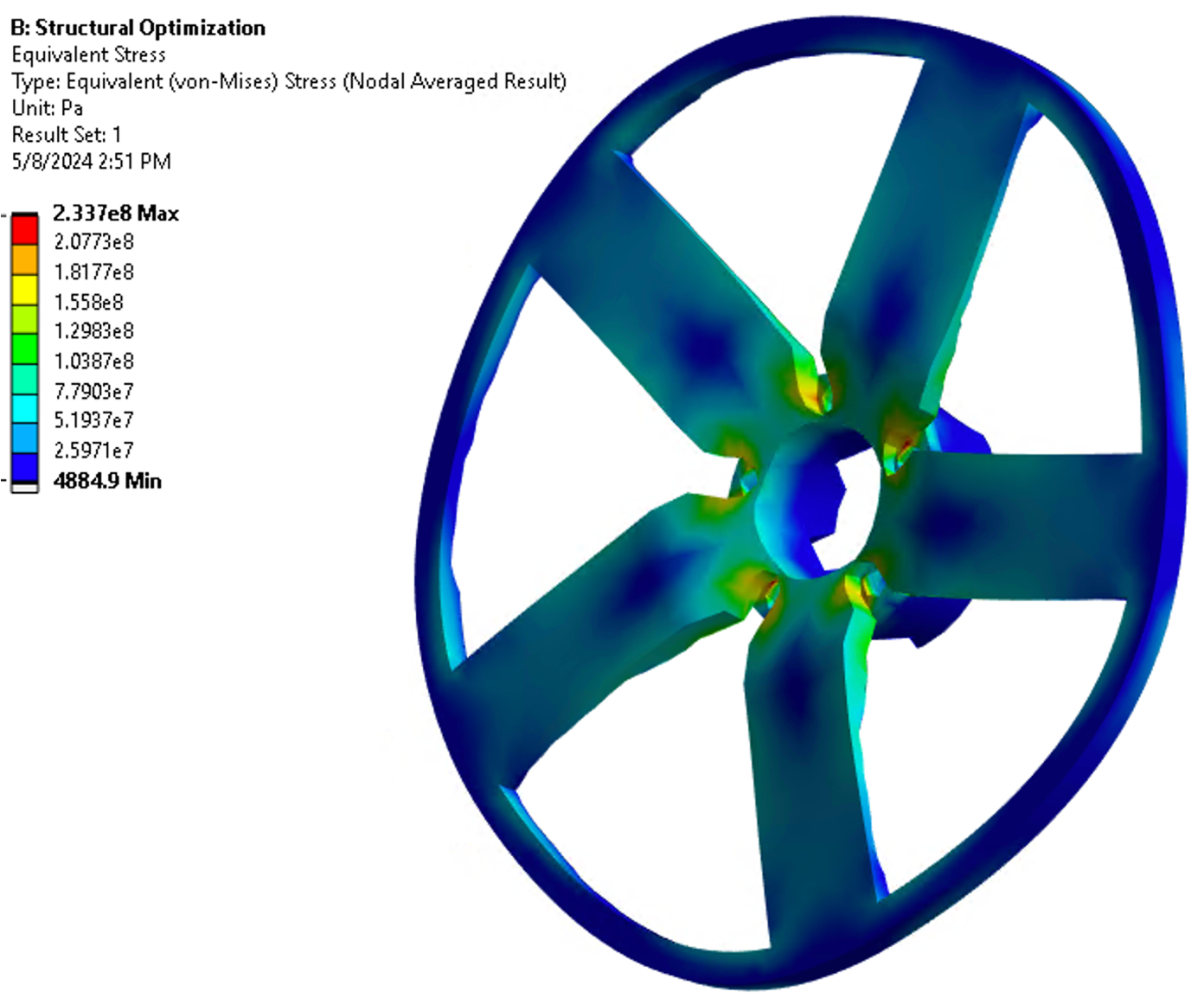
The optimization phase focused on balancing structural integrity with material reduction. Torque and loads were applied to simulate realistic conditions, while bolt hole locations remained fixed. To ensure accurate results without overloading the system, I used finer mesh elements in areas with more intricate geometries and coarser meshes elsewhere. This approach improved efficiency without sacrificing precision in critical zones. The goal of the optimization was to meet the deformation and yield stress constraints while minimizing the mass of the wheel flange.
Results and Recommendations
The optimized design resulted in a mass reduction of approximately 20%, while still meeting the required deformation and yield strength limits for 6061 aluminum. The trade-off was a slight increase in deformation from the initial design, which allowed for a lower overall material usage. However, the final geometry was quite complex, which could present challenges in manufacturing. To address this, I proposed feasible adjustments—such as removing material from the supporting bars and central sections of the flange—to simplify the manufacturability without significantly impacting performance of the reduced-mass design.
Final Presentation
I gathered all of the work for the whole process and compiled it into an easy-to-digest presentation. The presentation is shown below and has the CAD & FEA images, detailed boundary conditions, and descriptions of the optimization process.