Using the Method of Characteristics to Design a 2D Nozzle
MATLAB Fluid Dynamics Propulsion
Project Overview
I developed a MATLAB-based software tool that utilizes Object-Oriented Programming to design an optimal 2D supersonic nozzle. The tool is built around the Method of Characteristics (MoC), a technique that transforms complex partial differential equations (PDEs) governing supersonic, steady, irrotational, inviscid, and isentropic flows into a system of ordinary differential equations (ODEs). By leveraging the hyperbolic nature of the governing equations, my tool systematically traces Mach waves starting from the nozzle throat, calculating characteristic points along the flow path. These characteristic lines define regions of continuous flow properties, allowing for precise nozzle contouring that eliminates shocks and ensures efficient expansion to the desired design altitude. Additionally, Prandtl-Meyer expansion theory is incorporated to compute flow properties at each characteristic intersection, optimizing the nozzle shape for maximum performance.
Key Design Features and Methodology
-
Supersonic, Steady, Irrotational, Inviscid, Isentropic Flow
The tool models the flow conditions of the nozzle based on these fundamental assumptions to ensure accurate supersonic flow analysis. -
Perfect Nozzle (Axisymmetric)
The design assumes an axisymmetric nozzle, ensuring consistent flow expansion and contraction. -
Mach Waves and Characteristic Points
The tool plots Mach waves starting from the throat, using the kickoff angle to calculate characteristic points along the nozzle flow path. -
Shock-Free Flow Design
The nozzle shape is optimized by determining the angle required to create a shock-free flow. -
Prandtl-Meyer Expansion Theory
The Prandtl-Meyer equation is used to compute flow properties at each characteristic intersection.
Technical Implementation
I applied and honed my skills in MATLAB programming to streamline computations for scalability and ease of use. The project involved:
- Implementing numerical solvers to solve the system of ODEs governing the flow.
- Creating visualization tools to plot characteristic lines and nozzle contours, offering clear graphical representations of flow properties and nozzle design.
- Designing an interactive GUI that allows users to input flow conditions and automatically generate nozzle profiles.
Below, I have some screenshots of the tool, and feel free to click on the images to make them bigger:
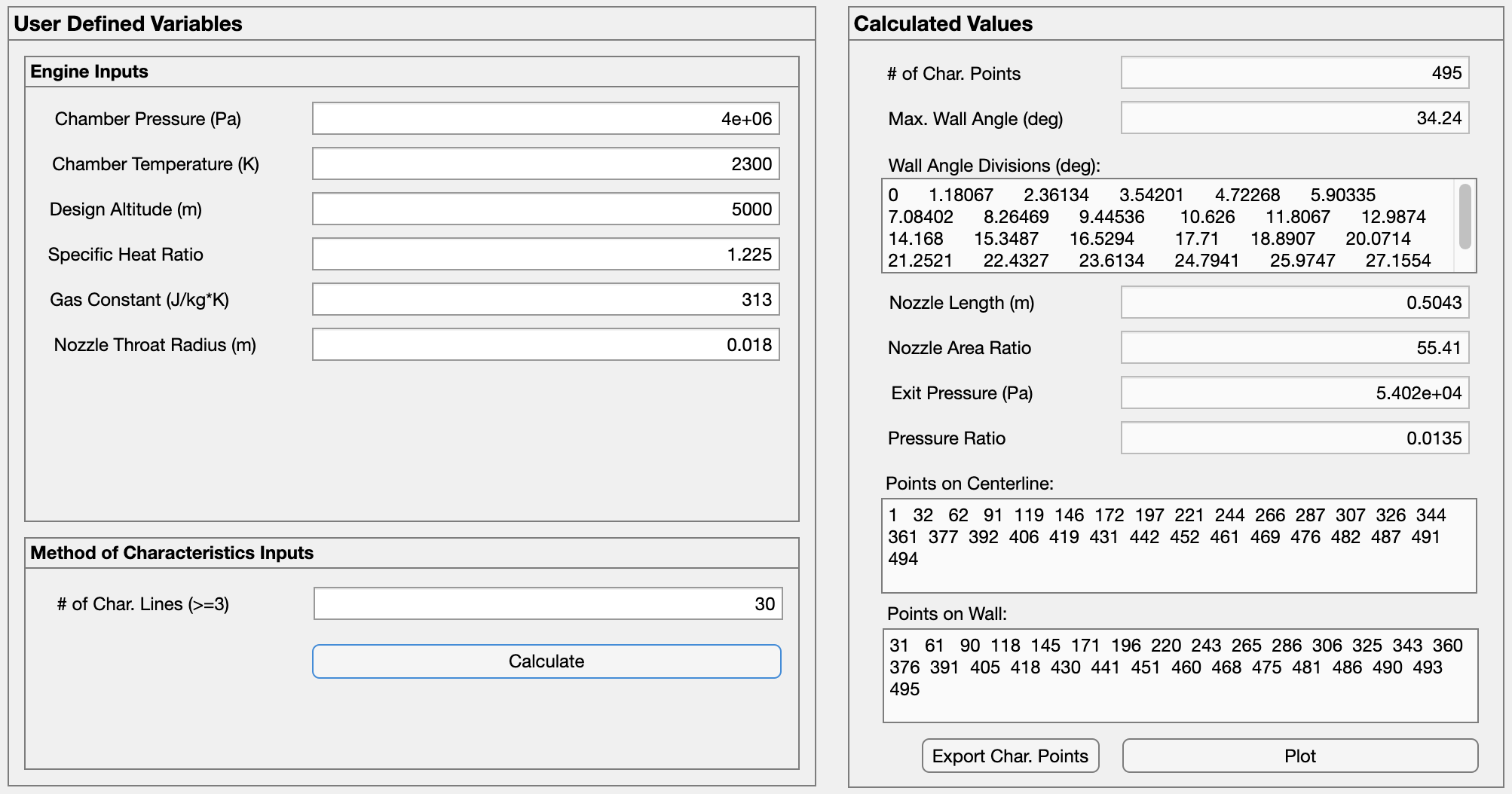
MATLAB GUI
The user will input the engine characteristics on the left along with the number of lines to use for the simulation. The right shows all of the results, along with options to export the points (useful for CAD and/or CFD modeling) or to plot it in MATLAB.
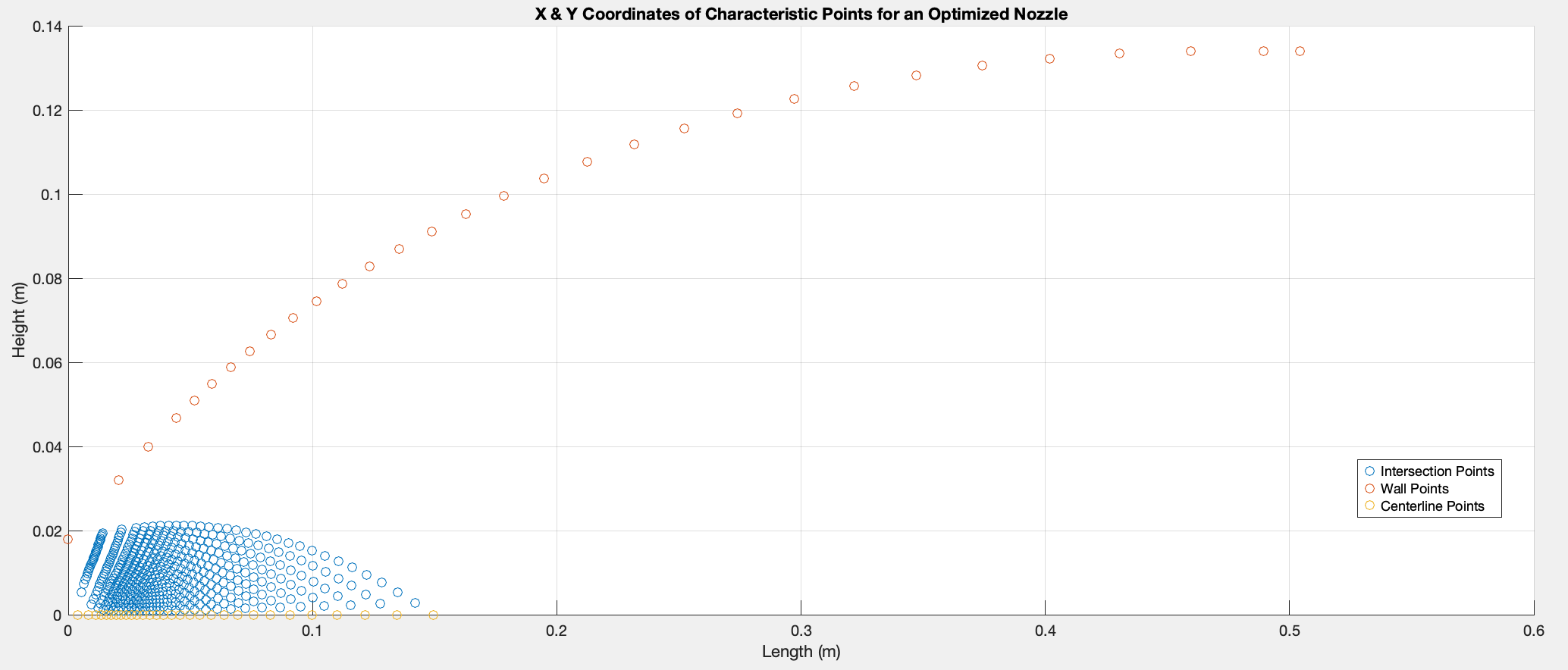
Characteristic Point Plot
Here is a plot with the red points showing the wall of the nozzle, the blue points showing the intersections of the characteristic lines, and the yellow points highlighting the centerline of the nozzle.
Next Steps: CFD Analysis
Next, I plan on exporting the plotted points into ANSYS Fluent to do CFD Analysis. Stay tuned for an update!